Life Cycle of Embedded System
In 2026, embedded systems power everything around us — from smart TVs, EV control units, and industrial robots to medical wearables and consumer IoT gadgets. With AI/ML integration, OTA updates, and real-time constraints becoming mainstream, the life cycle of an embedded system has evolved dramatically.
Introduction — Life Cycle of Embedded System
In 2026, embedded systems are at the heart of every smart product — from EV control units and industrial robots to IoT appliances and wearable medical devices. As products become more connected, intelligent, and software-driven, their lifecycle management has become more complex and more important than ever.
Whether you are building a consumer IoT gadget, a safety-critical automotive ECU, or a medical device, a well-structured embedded system lifecycle ensures performance, safety, reliability, and long-term maintainability. This guide explores the complete lifecycle and why it matters in today’s fast-evolving tech landscape.
What Is an Embedded System? Simple Explanation for Beginners
An embedded system is a specialized combination of hardware and software designed to perform a dedicated function within a larger device. It typically includes:
- A microcontroller or processor
- Memory and storage
- Sensors, actuators, or interfaces
- Firmware or real-time software
Unlike general-purpose computers, embedded systems are purpose-built, resource-constrained, and often required to operate reliably in real-time conditions.
Why Understanding the Lifecycle Matters in 2026
In 2026, embedded systems will be more advanced than ever — AI-enabled, cloud-connected, OTA upgradable, and used in safety-critical industries. Because of this, lifecycle management is not optional; it is essential.
Understanding the lifecycle helps engineers and companies:
- Build high-quality and secure devices
- Reduce development costs and time-to-market
- Avoid hardware/software integration issues
- Ensure compliance with new-age global standards
- Manage long-term support, firmware updates, and EOL planning
- Create scalable and future-ready product designs
With cyber-security attacks rising, sustainability regulations tightening, and AI models entering even low-power MCUs, lifecycle awareness is the only way to build reliable embedded products.
Real-World Areas Where Lifecycle Management Is Critical
Automotive ECUs
Modern vehicles rely on 70–150+ Electronic Control Units, handling everything from braking and ADAS to battery management in EVs.
Lifecycle management is crucial because:
- Automotive standards (ISO 26262, AUTOSAR) require strict validation
- ECUs must run error-free for 10–15 years
- OTA updates and cybersecurity must be tightly controlled
- Component obsolescence can delay production
A structured lifecycle ensures safety, reliability, and long-term ECU performance.
IoT Devices
IoT devices operate in diverse, unpredictable environments — homes, industries, farms, healthcare, and more.
Lifecycle management ensures:
- Secure firmware and OTA support
- Energy-efficient design for battery-powered devices
- Scalable cloud integration
- Long-term update and patch management
- Smooth hardware–software coexistence
With billions of IoT devices in 2026, strong lifecycle control reduces vulnerabilities and improves user experience.
Smart Appliances
From smart TVs and washing machines to connected refrigerators and air conditioners, smart appliances depend heavily on embedded firmware.
Lifecycle management helps manufacturers:
- Deliver consistent performance
- Push new features via OTA updates
- Reduce post-sales failures
- Ensure cost-optimised production
- Keep devices secure against cyber threats
A solid lifecycle strategy improves brand reliability and reduces service costs.
Medical Devices
Medical devices — infusion pumps, diagnostic systems, wearables, and implantables — operate under strict regulatory standards.
Lifecycle management is vital to:
- Comply with IEC 62304, ISO 14971, FDA, MDR
- Ensure life-critical safety and accuracy
- Maintain real-time performance
- Handle long-term support and testing
- Manage hardware obsolescence and risk assessment
Proper lifecycle control ensures safety, reliability, and regulatory compliance for devices that impact human lives.
What Is the Life Cycle of an Embedded System?
The life cycle of an embedded system refers to the complete journey an embedded product goes through — from idea to design, development, testing, deployment, and long-term maintenance. Unlike general software, embedded systems combine hardware + firmware + real-time constraints, making their life cycle more complex and structured.
Simply put:
It’s the step-by-step process followed to build, test, and maintain an embedded device throughout its entire lifespan.
Simple Explanation
Imagine building a smart device — like a smartwatch, EV controller, medical wearable, or IoT sensor.
To make it work reliably, you follow a clear sequence of steps:
- Plan what the device should do
- Choose the correct hardware and software
- Design the electronics and write firmware
- Assemble and test all components
- Manufacture and launch the device
- Provide updates and long-term support
This complete journey is called the life cycle of an embedded system.
It ensures the product is safe, durable, energy-efficient, and performs exactly as intended — even in the real world.
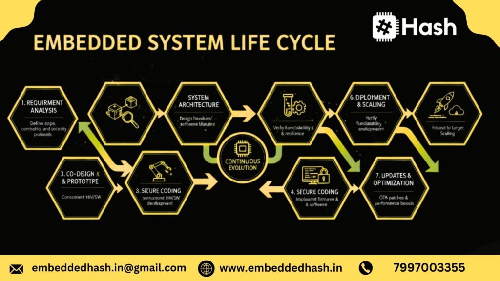
Overview of All Lifecycle Phases
Here’s a quick snapshot of the major phases involved in an embedded system’s life cycle (2026):
1. Requirement Analysis
Understanding what the system must achieve, performance targets, safety needs, and market expectations.
2. System Architecture & Design
Planning hardware, software, communication protocols, and power requirements.
3. Hardware Development
Creating schematics, designing the PCB, selecting components, and building prototypes.
4. Firmware/Software Development
Developing drivers, middleware, application firmware, and real-time logic.
5. Integration
Combining hardware + software and resolving conflicts such as timing issues and power fluctuations.
6. Testing & Validation
Ensuring the system is safe, reliable, EMI/EMC compliant, and meets industry standards (ISO 26262, IEC 62304, etc.).
7. Deployment & Production
Mass manufacturing, quality control, firmware flashing, packaging, and distribution.
8. Operation & Maintenance
Providing updates (OTA), bug fixes, diagnostics, and long-term support.
9. End-of-Life (EOL)
Handling component discontinuation, recycling, and migration to next-generation designs.
These steps ensure the product remains stable, secure, and future-ready, even after years of operation.
Why Embedded Lifecycle Is Different from Traditional SDLC
Embedded System Life Cycle ≠ Simple Software Development Life Cycle.
Here’s why they differ in 2026:
1. Hardware + Software Integration
Traditional SDLC deals only with software.
Embedded lifecycle must integrate physical hardware, sensors, and electronics.
2. Real-Time Constraints
Embedded devices must respond within microseconds (automotive braking, sensors, motors).
This makes timing a critical factor.
3. Resource Limitations
Embedded systems have limited CPU, RAM, flash, and power.
Software must be optimized for efficiency — unlike desktop/web apps.
4. Safety & Compliance Requirements
Industries like automotive, medical, and aerospace follow strict standards:
- ISO 26262
- IEC 62304
- DO-178C
- UL/FCC/CE certifications
Traditional software rarely faces such regulatory pressure.
5. Manufacturing & Production Phase
Embedded lifecycle includes physical manufacturing — PCB assembly, testing, flashing firmware.
SDLC has no equivalent stage.
6. Long-Term Maintenance + OTA Updates
IoT and automotive devices require updates for 10–15 years, even after production stops.
Traditional apps typically update only while in active use.
7. Environmental Testing
Embedded systems must survive heat, vibration, humidity, EMI, and power fluctuations.
This is not required in normal software development.
Final Summary
The life cycle of an embedded system is unique because it blends:
✔ Hardware engineering
✔ Firmware development
✔ Real-time performance
✔ Safety & compliance
✔ Manufacturing + long-term maintenance
This makes it far more comprehensive and engineering-heavy than traditional SDLC.
Phase 1 — Requirements Analysis
Requirements Analysis is the foundation of any embedded system project. In 2026, with IoT, AI-enabled edge devices, and global safety standards, this phase has become more structured and documentation-focused.
Functional vs. Non-Functional Requirements
Functional Requirements define what the system must do.
Examples:
- Measure temperature every 1 second
- Transmit sensor data via BLE
- Control a motor based on sensor thresholds
- Trigger an alert when the battery goes below 10%
Non-functional requirements specify the quality standards that determine how well a system should operate..
Examples:
- Power consumption < 150 mW
- System startup time < 200 ms
- Data transmission latency < 20 ms
- Operating temperature: –20°C to +80°C
- MTBF (Mean Time Between Failures) > 10,000 hours
Non-functional requirements decide the choice of microcontroller, OS, communication modules, and overall system architecture.
Real-Time Constraints & Safety Requirements
Embedded systems often need to respond within strict timing windows.
Real-time constraints include:
- Interrupt latency
- Task scheduling deadlines
- Sensor sampling rates
- Actuator response times
Safety Requirements (Critical in Automotive, Medical, Industrial):
- Fail-safe operation
- Watchdog timers
- Redundancy
- Secure boot & tamper-proof design
- MISRA C compliance
Industries like automotive follow ISO 26262, and industrial automation follows IEC 61508 for functional safety.
Example: IoT Smart Sensor Requirements
Functional Requirements:
- Sense temperature, humidity, and air quality
- Connect via Wi-Fi + BLE
- Push data to cloud (AWS/ThingsBoard) every 30 seconds
- Local OLED display for live readings
Non-Functional Requirements:
- Battery life: 6–12 months
- Size smaller than 60 × 40 mm
- Cost < ₹500 BOM for India market
- Must work in humid climate conditions
Safety & Regulatory:
- BIS Certification (India)
- CE/FCC for global deployment
- Secure OTA firmware update
Phase 2 — System Specification
System Specification translates raw requirements into detailed, measurable, and testable documents used by engineering teams.
Hardware Specification
This includes choosing the physical building blocks of the system:
- MCU/MPU (ARM Cortex-M4, ESP32-S3, STM32, RISC-V)
- Memory (Flash, SRAM, external PSRAM)
- Sensors (Temp, IMU, Pressure, Gas, Vision)
- Connectivity modules (Wi-Fi, BLE, Zigbee, CAN)
- Power system (battery, DC-DC converters, LDOs)
- Display types (LCD, TFT, OLED)
Specifications define exact models, ranges, tolerances, and electrical characteristics.
Software Specification
- Programming language (C, C++, MicroPython, Rust)
- RTOS (FreeRTOS, Zephyr, AUTOSAR OS)
- Drivers needed (GPIO, I2C, SPI, UART, ADC, PWM)
- Middleware (MQTT, TLS, OTA library, TCP/IP stack)
- Bootloader requirements
- AI/ML inference needs (TF Lite Micro, Edge Impulse DSP libs)
Communication & Interface Requirements
Define how the system talks internally and externally.
Examples:
- UART @ 115200 baud
- I2C @ 400 kHz for sensors
- CAN FD for automotive
- BLE 5.3 for configuration
- MQTT 3.1 or CoAP for cloud
Regulatory/Industry Standards (ISO 26262, IEC 61508)
Depending on industry:
- Automotive → ISO 26262
- Industrial Automation → IEC 61508
- Medical Devices → IEC 62304
- IoT Hardware → BIS, CE, FCC
- Software Safety → MISRA C / CERT C
These influence design choices, testing methods, and documentation depth.
Phase 3 — System Architecture Design
This phase creates the blueprint of the entire embedded system.
Hardware-Software Co-Design (Competitor Gap Opportunity)
Most competitor blogs ignore this — but it’s critical.
Co-design means designing hardware and software in parallel, not sequentially.Benefits:
- Perfect MCU selection for software complexity
- Lower BOM cost
- Optimized power consumption
- Reduced time-to-market
- Fewer redesign iterations
High-Level Hardware Architecture
Includes:
- MCU block diagram
- Sensor clusters
- Power supply tree
- Communication bus layout
- Memory map
- Reset circuitry and protection components
2026 trend: AI-enabled MCUs like ESP32-S3, STM32 NPU modules, and RISC-V AI cores.
Software Architecture (RTOS, Drivers, Middleware)
Architecture typically contains:
- Bootloader
- HAL/BSP layers
- RTOS scheduler
- Middleware stacks (MQTT, TLS, USB, TCP/IP)
- Application tasks
- OTA update module
- Logging & diagnostics module
Why Co-Design Matters in Embedded Systems
- Avoids costly hardware respins
- Ensures timing-critical tasks fit hardware limits
- Enables power-saving modes
- Aligns memory needs with MCU capabilities
Ensures secure and safety-certified architectures
- Perfect MCU selection for software complexity
Phase 4 — Hardware Development
PCB Design + Component Selection
Key activities:
- Schematic design
- PCB layout (2–8 layer boards)
- High-speed routing (USB, Ethernet, DDR)
- Impedance control
- BOM optimization for Indian and global suppliers
- Thermal and power calculations
Prototyping and Hardware Validation
Validation includes:
- Power rail checks
- Clock stability
- Sensor performance
- Communication interface testing
- Initial firmware flashing
EMI/EMC & Thermal Testing
Must comply with:
- CISPR standards
- CE/FCC radiation limits
- Thermal profiling (heat dissipation, hotspot mapping)
This ensures the board works safely, without interference.
Phase 5 — Software Development
Firmware Development (C, Embedded C++, MicroPython)
Firmware includes:
- Boot sequences
- Peripheral setup
- Interrupt routines
- Application logic
- Low-power states
- OTA support
C/C++ dominates, but MicroPython is rising for rapid IoT prototyping.
Driver Development & BSP
Drivers abstract hardware:
- I2C/SPI/UART drivers
- ADC, PWM, DMA
- Sensor drivers
- Display drivers
BSP ensures portability across boards.
Real-Time Operating System (RTOS) Integration
RTOS tasks include:
- Sensor task
- Communication task
- Display/UI task
- Logging task
Includes:
- Task scheduling
- Priority assignment
- Semaphore/mutex management
- Watchdog timers
Memory, Power, and Timing Optimization
Optimization techniques:
- Reduce flash & RAM usage
- Profile interrupt load
- Optimize loops and drivers
- Use deep sleep/ULP modes
- Minimize CPU wake-ups
2026 trend: AI-assisted code profiling tools.
Phase 6 — Deployment
Manufacturing & Production Testing
- Gerber and fabrication
- Assembly line setup
- ICT (In-Circuit Testing)
- AOI (Automated Optical Inspection)
- FCT (Functional Circuit Testing)
Firmware Flashing & Validation
- Secure flashing
- Version tracking
- Factory calibration
- Golden image programming
Field Installation
- Mounting
- Connectivity configuration
- Final QA
- Customer documentation
Phase 7 — Integration & Testing
Hardware-Software Integration
- Driver testing
- Peripheral validation
- Sensor calibration
- Communication testing
- Power measurement
Unit Testing, Functional Testing, System Testing
- Unit testing → Each function
- Functional testing → Each module
- System testing → Complete product
V-Model Testing Approach (Missing in Competitors)
V-Model ensures:
- Each requirement has a matching test
- Defects are caught early
- Safety compliance is easier
Used heavily in automotive and aerospace.
Testing Tools (JTAG, Logic Analyzer, Oscilloscope)
Common tools:
- JTAG/SWD (debugging & flashing)
- Logic analyzer (protocol debugging)
- Oscilloscope (signal analysis)
- Power analyzer (battery/power profiling)
Phase 8 — Maintenance & Updates
OTA Updates (Competitor Gap Opportunity)
Modern embedded systems require:
- Bug fixes
- Security patches
- Feature improvements
OTA includes:
- Delta updates
- Secure boot validation
- Rollback mechanism
Lifecycle Extension & Patch Management
- Component replacements
- Vulnerability patches
- Firmware upgrade roadmap
- Long-term support (LTS) models
Debugging Live Devices (Edge & Cloud Methods)
Debugging methods include:
- Remote logging
- Cloud dashboards
- Edge debugging via JTAG
- Real-time analytics (battery, memory, network)
Businesses rely on this to reduce downtime and extend device life.
Alternative Lifecycle Models Used in Embedded Systems
While the traditional embedded system life cycle follows a linear flow from requirements to maintenance, real-world engineering teams adopt different lifecycle models depending on project complexity, safety requirements, and time-to-market pressure. In 2026, the most widely used lifecycle models in embedded systems are the Waterfall Model, the V-Model, Agile–Embedded Hybrid, and the Product Life Cycle. Each serves a unique purpose and aligns with different industries such as automotive, IoT, healthcare, aerospace, and industrial automation.
Waterfall Model
The Waterfall Model is one of the earliest development models used in embedded engineering. It follows a strictly sequential flow where each phase must be completed before the next begins.
Why it’s used in Embedded Systems
Embedded systems have hardware dependencies, strict timelines, and regulatory requirements—making a structured model like Waterfall suitable for:
- Small-scale embedded devices
- Simple controllers
- Proof-of-concept prototypes
- Projects with stable, well-defined requirements
Advantages
- Clear documentation at every stage
- Easy to manage for fixed-scope projects
- Works well when hardware and environment are predictable
Limitations
- No flexibility once the project moves forward
- Late discovery of bugs (especially after hardware fabrication)
- Not suitable for fast-changing IoT and AI-driven systems
Despite its age, Waterfall still appears in many industries, especially in India, where legacy hardware and slow-changing industrial systems dominate.
V-Model (Most Relevant for Embedded & Automotive)
The V-Model is the most widely adopted lifecycle model in modern embedded, automotive, aerospace, and medical domains. It is essentially an enhanced version of Waterfall, focusing heavily on verification and validation at every stage.
Why It’s the Preferred Model in 2026
Industries like AUTOSAR, EV ECUs, ADAS, medical instruments, and avionics demand extremely high reliability. The V-Model ensures that each development phase has a matching testing phase.
Structure of the V-Model
- Left side (Development):
Requirements → System Design → Hardware/Software Design → Code - Right side (Testing):
Unit Testing → Integration Testing → System Testing → Validation
Advantages
- Strong alignment between design and test cases
- Early bug detection
- Mandatory compliance for safety standards like ISO 26262, IEC 62304, DO-178C
- Perfect for systems with real-time constraints and tight deadlines
Where It’s Used
- Automotive ECUs (ABS, ADAS, BMS, infotainment)
- Industrial automation
- Medical devices
- Avionics and aerospace
In short, the V-Model is the backbone of safety-critical embedded development in 2026.
Agile for Embedded (Hybrid Approach)
Pure Agile is difficult in embedded systems due to hardware limitations. However, in 2026, companies are adopting Agile–Embedded Hybrid Models to combine flexibility with hardware constraints.
How Agile Fits into Embedded Systems
- Software and firmware teams work in sprints
- Hardware teams follow a modified V-cycle
- Continuous Integration (CI) and automated testing
- Test-driven development (TDD) for firmware
- Early prototype boards (EVB/Dev Kits) allow iterative development
Benefits of Agile–Embedded Hybrid
- Faster releases, ideal for IoT and consumer electronics
- Rapid feedback loops
- Allows OTA updates and iterative improvement
- Better alignment between hardware, firmware, and cloud teams
Where It’s Popular
- IoT consumer products
- Smart home devices
- Wearables
- Robotics and drones
- AI-enabled edge devices
This model is becoming the default choice for startups and fast-moving embedded product companies globally.
Product Life Cycle (From Concept → End-of-Life)
While development models focus on engineering, the Product Life Cycle (PLC) covers the entire journey of an embedded product from market conception to shutdown or replacement.
1. Concept & Market Research
Identifying user needs, competitor analysis, pricing, and feasibility.
2. Development
Hardware design, firmware coding, integration, and testing—follows V-Model, Agile, or Waterfall.
3. Production
Mass manufacturing, certification, packaging, and logistics.
4. Deployment
Distribution to customers, onboarding, field testing, and performance monitoring.
5. Operation & Support
OTA updates, bug fixes, AI model tuning, and cloud monitoring dashboards.
6. End-of-Life (EOL) Management
- Component discontinuation tracking
- Migration to new MCUs or chipsets
- Data backup, recycling & sustainability compliance
- Launch of next-gen version
Why PLC Matters in 2026
Due to fast technology upgrades (AI accelerators, RISC-V MCUs, EV innovations), embedded products now have shorter life cycles and require proactive upgrade planning
Tools & Technologies Used in Each Lifecycle Phase
Modern embedded systems development relies heavily on advanced hardware, software, testing, and deployment tools. In 2026, the shift toward AI-enabled development, cloud-based debugging, and RISC-V adoption has expanded the toolchain across every stage of the lifecycle.
Below is a detailed list of the most commonly used tools, categorized for clarity and SEO strength.
Hardware Tools
Hardware tools support designing, building, and validating the physical embedded platform.
1. PCB Design & Simulation Tools
- Altium Designer – Preferred for high-speed, multi-layer, professional PCB design.
- KiCad (Open Source) – Ideal for startups and academic projects.
- Eagle CAD – Lightweight and commonly used for IoT, DIY, and prototyping.
- Mentor Graphics PADS / Xpedition – Used for automotive and aerospace-grade boards.
2. Schematic Capture Tools
- OrCAD
- EasyEDA
- DipTrace
3. Hardware Simulation & Modeling Tools
- LTspice → Analog circuit simulation
- Proteus → Microcontroller simulation + circuit visualizer
- Multisim → Popular for academic + industry circuit modelling
4. Prototyping & Debug Hardware
- Development Boards: STM32 Nucleo, ESP32-S3, Raspberry Pi, BeagleBone, Renesas RA, TI Launchpads
- Logic Analyzers: Saleae Logic, LogicPort
- Oscilloscopes: Rigol, Keysight, Tektronix
- Power Measurement Tools: Monsoon Power Monitor, Joulescope (for ultra low-power IoT)
5. Manufacturing Tools
- Pick-and-place machines
- Reflow ovens
- JTAG programmers
- Chip programmers: Segger Flasher, ST-Link, Xilinx Programmer
Firmware Tools
Firmware tools help write, compile, debug, and deploy embedded software.
1. IDEs & Compilers
- STM32CubeIDE (STM Microcontrollers)
- Keil uVision (ARM)
- IAR Embedded Workbench – Used for safety-critical industries
- Arduino IDE – For rapid prototyping & hobby projects
- PlatformIO – Modern, cloud-integrated embedded IDE
- Espressif IDF – ESP32 IoT applications
- MicroPython & CircuitPython IDEs – For Python-based embedded systems
2. Build Systems
- CMake – Cross-platform build automation
- Make / Ninja – Lightweight build tools
- SCons, Bazel – Increasingly adopted in 2026 for complex projects
3. Firmware Debuggers
- JTAG/SWD Debuggers:
- Segger J-Link
- ST-Link
- OpenOCD
- GDB-based Debugging
- Black Magic Probe (Open-source embedded debugging)
- Segger J-Link
4. RTOS & Middleware Tools
- FreeRTOS, Zephyr, ThreadX, RT-Thread
- MQTT, CoAP stacks
- TCP/IP middleware
- BLE, Wi-Fi stacks (ESP-IDF, Nordic SDK)
5. AI/ML Tools for Embedded (2026 Trend)
- TensorFlow Lite Micro
- Edge Impulse Studio
- TinyML tools (micro-NN optimizers)
- ONNX Runtime for Embedded Devices
Testing & Debugging Tools
Testing tools ensure reliability, compliance, and performance of the embedded product.
1. Static Analysis Tools
- MISRA Compliance Tools
- PC-lint
- Cppcheck
- Coverity
- Clang Static Analyzer
- PC-lint
2. Dynamic Testing Tools
- Valgrind
- Address Sanitizers
- Memory leak detectors for embedded systems
3. Protocol Analyzers
- CAN Analyzer (for Automotive)
- USB Analyzer
- I2C/SPI/UART Analyzers
4. Hardware Debugging Tools
- Digital storage oscilloscopes (DSO)
- Thermal cameras (for power/heat issues)
- Boundary-scan tools
5. Automated Testing Frameworks
- Robot Framework
- Google Test (gTest)
- Unity Test Framework (popular in embedded C)
6. Environmental & Compliance Testing Equipment
- Vibration test chambers
- Temperature cycling chambers
- EMI/EMC test benches
CI/CD for Embedded Systems (Rarely Covered by Competitors)
CI/CD is becoming a mandatory requirement in 2026—especially for IoT, automotive, and large-scale firmware projects. It ensures continuous quality, rapid testing, and error-free deployment.
1. Popular CI/CD Platforms
- GitHub Actions
- GitLab CI
- Jenkins (Self-hosted)
- Azure DevOps Pipelines
- Bitbucket Pipelines
2. Embedded-Specific Integrations
- Docker cross-compilation for ARM, RISC-V, ESP32 builds
- Unit testing automation with Unity/gTest
- Static analysis integration (PC-Lint, Coverity, Cppcheck)
- Automated firmware flashing to test boards using:
- OpenOCD scripts
- J-Link Commander
- PyOCD
- OpenOCD scripts
3. Hardware-in-the-Loop (HIL) Testing
Automated framework where CI pipeline:
- Builds firmware
- Deploys to a physical board
- Runs automated scripts
- Captures logs + power consumption + performance metrics
Common HIL setups:
- NI PXI Systems
- Raspberry Pi–controlled test rigs
- Custom robotic arms for keypad/display testing
4. OTA Build Pipelines (IoT Trend 2026)
CI/CD pipelines generate secure OTA bundles and push them to:
- AWS IoT Device Management
- Azure IoT Hub
- Golioth Cloud
- Mender.io (popular for Linux devices)
5. Benefits of CI/CD in Embedded
- Faster development cycles
- Zero-downtime firmware deployment
- Standardized QA process
- Early bug detection
- Lower production failures
Very few competitors explain CI/CD for embedded systems—this is your SEO advantage.
If you want to Learn more About Embedded Systems, join us at Embedded Hash for Demo Enroll Now
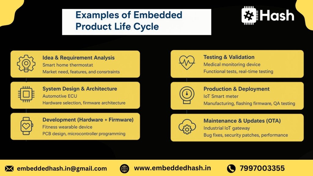
Real-World Case Study: Examples of Embedded Product Life Cycle
To understand the embedded system life cycle practically, let’s walk through a real-world example. This case study shows how each phase works in an actual engineering scenario — from concept to deployment and long-term maintenance.
Example: Smart Home Wearable or IoT Sensor
Imagine a Smart Home Health Wearable — a compact device that tracks temperature, heart rate, room humidity, and movement, sending real-time data to a mobile app using BLE or Wi-Fi.
This product is perfect for:
✔ Home automation
✔ Elderly care
✔ Health monitoring
✔ Smart living use cases (India + global markets)
Step-By-Step Walkthrough of Each Lifecycle Phase
1. Requirement Analysis
- Must collect: heart rate, temperature, steps, humidity
- Battery must last at least 5–7 days
- Data must sync via Bluetooth and optionally Wi-Fi
- Cost target: Highly competitive for Indian consumer market (< ₹2,000 BOM)
- Compliance: CE, BIS, Bluetooth certification
2. System & Architecture Design
- MCU selection: ESP32-S3 (Wi-Fi + BLE + low power)
- Sensors: MAX30102 (pulse), BME280 (temp + humidity), accelerometer
- OS: FreeRTOS for real-time tasks
- Power Supply: Li-ion battery + charging IC
- App Integration: Android/iOS Bluetooth API
- Security: AES-based encryption + secure boot
3. Hardware Development
- Schematic design created using Altium/KiCad
- 4-layer compact PCB layout
- Prototyping manufactured using rapid PCB service
- Hardware bring-up verifies sensors, antenna performance, battery charging
4. Firmware & Software Development
- Driver code for MAX30102, BME280, accelerometer
- BLE GATT services for data packet streaming
- FreeRTOS tasks for sensor polling, event handling, low-power mode
- Sleep mode optimization → 40% improved battery life
- AI model integration (optional): anomaly detection on-device
5. Integration (Hardware + Software)
- Firmware flashed onto prototype board
- Real sensor readings cross-checked
- Latency measurements taken for BLE data transfer
- Antenna tuning performed for improved signal strength
- Mobile app tested with real-time data
6. Testing & Validation
Functional Tests:
- Sensor accuracy across temperature variations
- Bluetooth connectivity range
- Battery performance under stress
Compliance Tests:
- EMI/EMC for home appliances
- BIS for Indian consumer certification
Environmental Tests:
- Sweat, moisture, drop tests for wearable use
7. Mass Production & Deployment
- EMS partner selected (Hyderabad, Pune, or Shenzhen)
- Firmware locked + secure boot keys added
- Automated production line testing configured
- Packaging optimized for low shipping cost=
8. Operation, OTA & Maintenance
- Cloud dashboard collects anonymized data
- Weekly OTA updates delivered
- App notifies user for battery issues or sensor faults
- Predictive maintenance: detects failing sensors early
9. End-of-Life & Upgrade Plan
- Next-gen hardware planned with AI accelerators
- Legacy support for 3 years
- E-waste compliant recycling processes
This case study shows how embedded systems follow a full, iterative, and future-proof lifecycle, especially in fast-growing IoT markets like India, Europe, and the US.
Future Trends in Embedded System Development (2026–2030)
The next five years will revolutionize how embedded systems are designed, tested, and maintained. AI, cloud, and digital engineering will deeply reshape the development pipeline.
Below are the top future trends shaping embedded engineering globally.
AI-Driven Lifecycle Automation
AI will automate large portions of the embedded system lifecycle:
- AI-assisted hardware design (auto-generating schematics + PCB layout)
- AI-driven firmware suggestions (code generation, driver optimization)
- Self-healing firmware that detects anomalies and repairs itself
- AI-based test automation replacing manual validation
By 2030, up to 40% of embedded development tasks may be AI-assisted, increasing speed and reducing human error.
Digital Twins for Embedded Systems
Digital twins are virtual replicas of embedded systems that simulate hardware + software behavior before actual deployment.
Benefits:
- Detect hardware issues before manufacturing
- Test firmware without physical boards
- Reduce prototype iterations
- Improve AI model training with simulated data
Industries adopting digital twins fastest:
✔ Automotive (ADAS, EV BMS)
✔ Industrial automation
✔ Aerospace
✔ Smart city devices
By 2030, digital twins may reduce development time by 30–50%.
Cloud-Connected Embedded Devices
Cloud connectivity will be the default for modern embedded systems.
Key advancements:
- Real-time device monitoring
- Remote configuration & debugging
- Cloud-based ML inference
- Cross-device data sharing
- Scalable IoT fleet management
Platforms like AWS IoT, Azure Sphere, GCP IoT Edge, and India-based cloud IoT platforms are rapidly expanding.
Next-Gen OTA and Predictive Maintenance
OTA in 2026–2030 will evolve far beyond simple firmware updates.
New capabilities:
- Delta-only OTA (smaller update size)
- Dual-bank secure OTA with rollback
- Predictive maintenance using ML models
- OTA for safety-critical devices (EVs, healthcare)
- Multi-device synchronized OTA in factories
Predictive maintenance will use AI to identify:
- Battery degradation
- Sensor drift
- Component failures
- Wearable usage anomalies
This helps reduce downtime and extends product life.
Conclusion - Life Cycle of Embedded System”
The life cycle of an embedded system in 2026 is far more advanced, interconnected, and quality-driven than ever before. With increasing adoption of IoT, AI at the edge, automotive electronics, medical-grade systems, and smart industrial automation, the demand for structured development models has become essential.
From defining crystal-clear requirements to choosing the right architecture, validating through industry standards, integrating hardware–software, and managing OTA updates post-deployment — each phase plays a critical role in building a reliable and future-proof embedded product.
Different lifecycle models such as the Waterfall Model, V-Model, Agile–Embedded Hybrid, and the Product Life Cycle serve unique purposes depending on complexity, safety needs, and time-to-market requirements. Among these, the V-Model remains the gold standard for safety-critical domains, while Agile hybrids dominate the IoT and consumer electronics space.
As embedded technologies evolve with RISC-V processors, AI accelerators, low-power designs, enhanced security, and Make-in-India manufacturing, understanding the complete lifecycle has become a core skill for engineers, product developers, and organizations.

Frequently Asked Questions
The life cycle of an embedded system is the complete journey of a product—from requirement analysis, design, hardware development, firmware creation, testing, deployment, to maintenance and end-of-life. In 2026, this process also includes OTA updates, AI/ML integration, security validation, and cloud connectivity.
A well-defined life cycle ensures the product is reliable, safe, cost-efficient, and compliant with global standards. It reduces development risks, prevents failures in the field, and helps teams build scalable, future-ready embedded solutions.
The major phases include:
- Requirement Analysis
- System Design
- Hardware Development
- Firmware/Software Development
- Integration
- Testing & Validation
- Deployment
- Operation & Maintenance
- End-of-Life & Upgrades
Development time varies by complexity:
- Simple microcontroller products: 1–3 months
- IoT devices: 4–9 months
Automotive/Medical systems: 12–24 months
Compliance testing and certification often extend timelines.
Common challenges include memory constraints, real-time performance requirements, power optimization, hardware–software integration issues, security implementation, and compliance with standards like ISO 26262 or IEC 62304.
Testing verifies reliability, safety, and performance under various conditions. In 2025, testing covers EMI/EMC, security penetration tests, real-time behavior, OTA update validation, and AI/ML model accuracy for intelligent devices.
Current trends include:
- AI/ML at the edge
- RISC-V adoption
- Secure boot + encryption
- OTA updates as a default feature
- Low-power design and sustainability
- Integration with cloud IoT platforms
These advancements have added new stages and responsibilities to the life cycle.
Embedded development focuses on hardware + firmware inside a device.
IoT development adds layers like cloud connectivity, dashboards, remote monitoring, OTA updates, and cybersecurity. The IoT life cycle is an extended version of embedded system development.
Required skills include Embedded C/C++, RTOS, microcontroller programming, hardware debugging, communication protocols (SPI, I2C, UART, CAN), Linux basics, AI/ML integration, power optimization, and understanding safety standards
Maintenance includes bug fixes, firmware OTA updates, security patches, battery optimization, real-time monitoring, sensor calibration, and long-term support for hardware/firmware versions.
Over-The-Air (OTA) updates allow developers to update firmware remotely. This reduces service costs, enhances security, adds new features, and fixes bugs without requiring physical access to the device.
If you want to Learn more About Embedded Systems, join us at Embedded Hash for Demo Enroll Now

 embeddedhash.in@gmail.com